All about HP Virtual Connect FC module…..
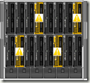
This is how VC FC module looks like…, and you install them in redundant pairs in adjacent interconnect bays at the rear of the chassis.
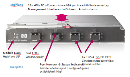
You then patch each of the FC Ports into a FC switch.
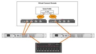
The supported configuration is one FC-VC Module to 1 FC switch (below)

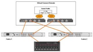
Connecting one VC module to more than one FC switch is unsupported (below)

So, in essence you treat each VC module as terminating all HBA Port 1′s and the other FC-VC module as terminating all HBA Port 2′s.
The setup we had:
- A number of BL460c blades with dual-port Qlogic Mezzanine card HBAs.
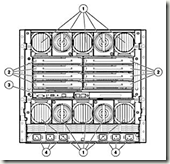
- HP c7000 Blade chassis with 2 x FC-VC modules plugged into interconnect bay 3 & 4 (shown below)
The important point to note is that whilst you have 4 uplinks on each FC-VC module that does not mean you have 2 x 16Gb/s connection “pool or trunk” that you just connect into.
Put differently if you unplug one, the overall bandwidth does not drop to 12Gb/s etc. it will disconnect a single HBA port on a number of servers and force them to failover to the other path and FC-VC module.
It does not do any dynamic load balancing or anything like that – it is literally a physical port concentrator which is why it needs NPIV to pass through the WWN’s from the physical blade HBAs.
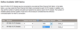
There is a concept of over-subscription, in the Virtual Connect GUI that’s managed by setting the number of uplink ports used.
Most people will probably choose 4 uplink ports per VC module, this is 4:1 oversubscription, meaning each FC-VC port (and there are 4 per module) has 4 individual HBA ports connected to it, if you reduce the numeber of uplinks you increase the oversubscription (2 uplinks = 8:1 oversubscription, 1 uplink = 16:1 oversubscription)
Which FC-VC Port does my blade’s HBA map to?
The front bay you insert your blade into determines which individual 4Gb/s port it maps to and shares with other blades) on the FC-VC module, its not just a virtual “pool” of connections, this is important when you plan your deployment as it can affect the way failover works.
the following table is what we found from experimentation and a quick glance at the “HP Virtual Connect Cookbook” (more on this later)
| FC-VC Port | Maps to HBA in Blade Chassis Bay, and these ports are also shared by.. |
| Bay3-Port 1, Bay-4-Port 1 | 1,5,11,15 |
| Bay3-Port 2, Bay-4-Port 2 | 2,6,12,16 |
| Bay3-Port 3, Bay-4-Port 3 | 3,7,9,13 |
| Bay3-Port 4, Bay-4-Port 4 | 4,8,10,14 |

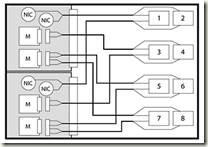
Each individual blade has a dual port HBA, so for example the HBA within the blade in bay 12 maps out as follows
HBA Port 1 –> Interconnect Bay 3, Port 2
HBA Port 2 –> Interconnect Bay 4, Port 2
Looking at it from a point of a single SAN attached Blade – the following diagram is how it all should hook together

Path Failover
Unplugging an FC cable from bay 3, port 4 will disconnect one of the HBA
connections to all of the blades in bays 4,8,10 and 14 and force the blade’s host OS to handle a failover to its secondary path via the FC-VC module in bay 4.
A key take away from this is that your blade hosts still need to run some kind of multi-pathing software, like MPIO or EMC PowerPath to handle the failover between paths – the FC-VC modules don’t handle this for you.

FC Loading/Distribution
A further point to take away from this is that if you plan to fill your blade chassis with SAN attached blades, each with an HBA connected to a pair of FC-VC modules then you need to plan your bay assignment carefully based on your server load.
Imagine if you were to put heavily used SAN-attached VMWare ESX Servers in bays 1,5,11 and 15 and lightly used servers in the rest of the bays then you will have a bottleneck as your ESX blades will all be contending with each other for a single pair of 4Gb/s ports (one on each of the FC-VC modules) whereas if you distributed them into (for example) bays 1,2,3,4 then you’ll spread the load across individual 4Gb/s FC ports.
Your approach of course may vary depending on your requirements, but I hope this post has been of use.
There is a very, very useful document from HP called the HP Virtual Connect Fibre Channel Cookbook that covers all this in great detail, it doesn’t seem to be available on the web and the manual and online documentation don’t seem to have any of this information, if you want a copy you’ll need to contact your HP representative and ask for it.
출처 : https://vfella.wordpress.com/2014/09/11/all-about-hp-virtual-connect-fc-module/
HP 블레이드 서버에서 I/O 확장을 위해 사용하는 블레이드 메자닌 카드
HP블레이드 메자닌 카드는 블레이드 서버의 시스템 보드에 일체형으로 장착할 수 있는 변형된 PCI-express 방식의 I/O카드 이다.


기존 서버에 사용되던 일반적인 PCI 방식의 카드는 컨트롤러를 포함한 보드 부분과 외부 I/O연결을 위한 포트 부분이 일체형으로 구성되어 있지만
블레이드 서버의 메자닌 카드는 I/O 포트 부분이 분리되어 인터커넥트로 대체되고 오직 컨트롤러 보드만 존재하는 형태로 구성된다.
이렇게 I/O 포트 부분이 제거된 매자닌 카드는 인클로저의 미드플레인을 거쳐 후면부 인터커넥트를 통해 외부 I/O와 연결될 수 있다.
참고로 외부I/O 연결을 위한 매자닌 카드는 인터커넥트의 이중화 구성을 위해 일반적으로 2 port or 4 port 카드로 제공된다.
PCI-e 규격에 따라 다양한 레인의 속도를 지원한다. 예를들어 타입 1 카드 슬롯은 PCI-e 4 레인을 지원하고 타입 2 카드 슬롯은 PCI-e 8 레인을 지원한다.
HP 블레이드 서버에 장착가능한 메자닌 카드는 서버들간의 데이터 전송을 위한 이더넷 네트워크 카드, 서버와 스토리지 간에 데이터 전송을 위한 스토리지 네트워크 카드, 하이 퍼포먼스 컴퓨팅 분야에서 고속의 데이터 전송을 지원하는 인피니밴드 카드, 그리고 스토리지 블레이드 또는 테이프 블레이드를 다이렉트로 연결할 수 있는 PCI-e PASS-Through 카드 등 다양한 종류를 지원하고 있다.
블레이드 서버에 탑재된 메자닌 카드 슬롯의 포트와 인터커넥트 베이 사이에는 사전에 정의된 연결 규칙이 존재한다.
예를들어 C7000, C3000과 같은 블레이드 인클로저의 종류, 풀 하이트 하프 하이트와 같은 블레이드 서버의 크기, 메자닌 카드의 슬롯 번호, 그리고 메자닌 카드의 포트 개수 등 다양한 조건에 따라 메자닌 카드 포트와 연결되는 인터커넥트 베이의 위치가 설계시 부터 최적화 되어 구성되었다. 따라서 사전에 정의된 인터커넥트베이의 연결 구조를 숙지하여 블레이드 시스템의 I/O를 계획하고 구성 해야 한다.
'ㆍ Unix' 카테고리의 다른 글
| GBIC, SFP (0) | 2022.05.12 |
|---|---|
| [Unix, HP-UX] 유닉스 bdf, 디스크 사용량 보기 (2) | 2020.08.20 |